Thursday 24 October 2013

Potential divider


Potential Dividers
The potential divider is at its simplest two series resistors connected to a battery and the voltage is measured between the negative terminal and a point between the two resistors.


You can treat this circuit as two resistors in series, working out the total resistance, the current, then working out the voltage across R2.  However you can use the potential divider equation:

You don't have to have fixed value resistors.  Variable resistors and components like thermistors and light dependent resistors are put into potential divider circuits.  You can use a piece of resistance wire between to fixed points and move a slider to any point between them. 


by aymeric


Tuesday 15 October 2013

Kirchoff's Second Law

Kirchoff's Second Law


KIRCHOFF'S FIRST LAW ;
It states that the sum of currents entering any junction is the same as the amount exiting the junction.
This conserves CHARGE!


KIRCHOFF'S SECOND LAW ;
It states that in any closed loop the sum of the p.d's must equal the sum of the e.m.f's within the loop.
This conserves ENERGY!


Blog by Harshil Patel


Thursday 10 October 2013

DC Circuits Basic


Circuits
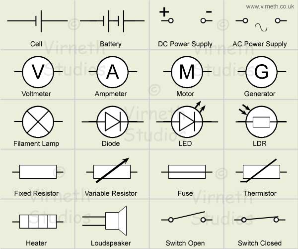
A DC circuit is a circuit with a direct current. A circuit consists of many different components and each of these has a symbol which we use so that anyone which any language can see and identify the component just by its symbol, some of these are:
This means there is no language barrier when it comes to working with circuits. The use of symbols also allow us to use them (in diagrams) before setting up circuits so we know how the circuit is laid out and what needs to go where to obtain what results.

Series circuit                                                                                      
In a series circuit there is one loop of current from the power supply at the negative terminal back to positive terminal, this means that there are no extra components in an extended branch coming off any of the series wires.
Parallel circuit                                                                                                                                             In a parallel circuit the circuit has extra sets of components coming out from the original series loop.

The diagram on the top is the series circuit which has all the components in one loop without any extra wires connecting any external components; we say that all the components are in series with the power supply. The diagram on the bottom is a parallel circuit which has extra wires connected a lamp to the original series circuit. We say that the lamp is in parallel with the other lamp. 
                            
By Munawar Ali Khan

Wednesday 2 October 2013

Power!

Power!


In physics, power (symbol: P) is defined as the amount of energy consumed per unit time. In the MKS system, the unit of power is the joule per second (J/s), known as the watt (in honour of James Watt, the eighteenth-century developer of the steam engine). For example, the rate at which a light bulb converts electrical energy into heat and light is measured in watts—the more wattage, the more power, or equivalently the more electrical energy is used per unit time.


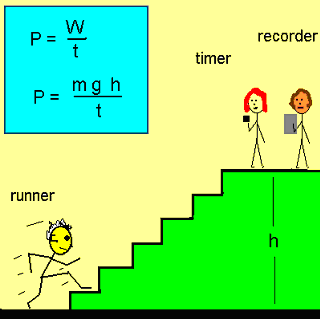
Energy transfer can be used to do work, so power is also the rate at which this work is performed. The same amount of work is done when carrying a load up a flight of stairs whether the person carrying it walks or runs, but more power is expended during the running because the work is done in a shorter amount of time. The output power of an electric motor is the product of the torque the motor generates and the angular velocity of its output shaft. The power expended to move a vehicle is the product of the traction force of the wheels and the velocity of the vehicle.

The dimension of power is energy divided by time. The SI unit of power is the watt (W), which is equal to one joule per second.

Blog entry of Saif Rehman

Tuesday 1 October 2013

Resistance


Resistance is potential difference per unit current and the equation is:

Resistance = potential difference/current

Therefore resistance must be measured in volts per ampere. The SI unit is known as ohm. We use the capital Greek letter (omega) Ω to represent it.
So if a component has a potential difference of 4V and a current of 2A, the resistance would be:
4/2=2Ω (ohms)

When an electron moves across a wire, resistance is produced because the electron does not take a straight route through it. It will have lots of collisions and that will cause resistance. Resistance is a hindrance to the flow of charge.