Saturday 28 September 2013

Fuses & Kilowatt-hour


Learning Objectives:
1-Explain how a fuse works and determine the correct fuse for an electrical device.
2-Define the kilowatt-hour.


Keywords (page 108-109 in the orange book):
1-Current is a flow of current, measured in ampere(A).
2-Power is the rate of doing work, measured in watts(W).
3-Fuse is an electric component designed to heat up, melt and break a circuit.
4-Joules is an unit of energy (J)
5-Kilowatt-hour is an unit of energy(KWh)


Fuse

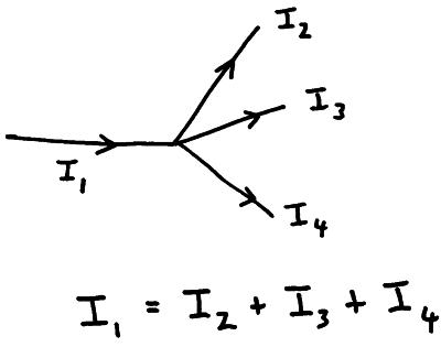
A  fuse is an electrical component that is designed to heat up, melt and break the circuit (to stop the current) when a specified amount of electric current passes through it. It is  used as a safety device.
The fuse breaks the circuit if the current is too high. this protects the component and the user if something goes wrong. 
there are three common types of fuses and they are 3A, 5A and 13A. 
The fuse used should be slightly higher than the current passing through the component such as a 3A fuse should be used for a current of 2A.

How to chose which fuse to use:
P=VI
P-Power in watts(W)
V-Voltage (V), the standard voltage is 230V in England


I-Current in amps(A) 

The 3 types of fuses used
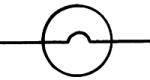
The circuit breaker

The circuit breaker does the same job as the fuse, but works in a different way. A spring-loaded push switch is held in the closed position by a spring-loaded soft iron bolt. An electromagnet is arranged so that it can pull the bolt away from the switch. If the current increases beyond a set limit, the electromagnet pulls the bolt towards itself, which releases the push switch into the open position.
A circuit breaker.
A circuit breaker in a home.

Kilowatt-hour

A kilowatt-hour (KWh) is 1000 watts used for 3600 second (constantly) it is therefore 3 600 000 J. This is because 1KW=?J/t
KW-Kilowatt
t-Time (s)
?J-Unknown energy (this become KWh when re-arranging the formula to become KWh=KW/t).    
Energy
E
=
Power
P
x
Time
t
(kWh)
(kW)
Remember the power must be in kilowatts (thousands of watts - in all other physics calculations it must be in watts)
(h)
Remember the time must be in hours (in all other physics calculations it must be in seconds)
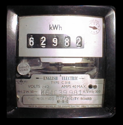
This monitors how many Kilowatt-hours you use at home.


1KWh costs 12p (£0.12). to work out how much 23KWh cost all you have to do is 23*0.12=£2.76


Questions-(Rember to use the standard of 230V)

Awnser questions in the comment area below.

Fuses

Q1. What fuse is necessary for a cooker which has 3 hotplates, each of 1.2KW, and one of 1.5KW, a grill of 1.6KW and an oven of 1.8KW?
Q2.Which fuse would be the best to use in a plug for a 3A table lamp?


Kilowatt-hour

Q3.A washing machine has a power-rating of 2500W. If a unit of electricity costs 24p, how much does it cost to run the appliance for 90 minutes?
Q4.A vacuum cleaner has a power-rating of 1.2kW. If a unit of electricity costs 20p, how much does it cost to run the appliance for a year if it is switched on for 1 hour each day?
Q5.A hair drier has a power-rating of 750W. If a unit of electricity costs 21p, how much does it cost to run the appliance for a year if it is switched on for 10 minutes each day?
By Harshil 

Friday 27 September 2013

The effect of temperature on resistivity

Usually resistance depends on three things, the material, the length and the area. However, heat affects resistance, the higher the temperature the higher the resistance.

When you cool a certain material to the point where it reaches its critical temperature, it's resistance would equal zero. But if you increase its temperature, you'd give more energy to its atoms, thus increasing the number of collisions between them resulting in increasing the resistance.

The resistance of R of many metals is directly proportional to the temperature T in kelvin.
As Temperature increases, Resistivity increases, resistivity of the material increases and current decreases.

T ^, R ^, p ^, I v


A thermistor is a solid-state device, similar in many ways to an LED, but does not emit light. Usually made from silicon containing a small number of impurity atoms, it's resistance is highly temperature dependent, altering far more than that of any metal for a given change in temperature.

One widely used NTC thermistor has a resistance of 9000Ω at 0C and 240Ω at 100C


aymeric

Resistivity

What factors affect the resistance of a material?

a) Length - the further electrons have to travel through material, the more collisions they will have so the higher the value of resistance.

b) Area - a bigger area means that in any 1 second more electrons will be able to travel through a piece of wire. More electrons means more current which means less resistance.

c) Material - if you swapped all the copper wire in a circuit for wood you'd notice a lot less current and a lot more resistance in the circuit. The ability of a material to resist a current is called its resistivity, ρ. Resistivity is measured in ohm-metres ( Ω m).

d) Temperature - but I cover that in my next blog'.

So:.

R ∝ l

R ∝ l/A

R ∝ ρ

These can be combined to give:

R = ρl/A

Where:.

R = resistance (Ω)

ρ = resitivity of the material (Ω m)

I = length of wire (m)

A = cross-sectional area of the wire (m2)


The formula relating resistivity (ρ) to resistance (R), cross-sectional area (A) and length (L) is:

p=RA/L


Two videos Part 1
Part 2

Material

Resistivity

(ohm•meter)

Silver
1.59 x 10⁻⁸
Copper
1.7 x 10⁻⁸
Gold
2.4 x 10⁻⁸
Aluminum
2.8 x 10⁻⁸
Tungsten
5.6 x 10⁻⁸
Iron
10 x 10-8
Platinum
11 x 10-8
Lead
22 x 10-8
Nichrome
150 x 10-8
Carbon
3.5 x 10⁻⁵
Polystyrene
10- 1011
Polyethylene
10- 109
Glass
1010 - 1014
Hard Rubber
1013

1 Taking the resistivity of platinoid as 3.3 x 10⁻⁷ m, find the resistance of 7.0 m of platinoid wire of average diameter 0.14 cm.

2 The resistance of the ohm is very approximately that of a column of mercury 1.06 m long and of uniform cross-section of one hundredth of a cm2. Find the resistivity of mercury.

3 What length of German silver wire, diameter 0.050 cm, is needed to make a 28 resistor, if the resistivity of German silver is 2.2 x 10⁻⁷ m?

4 The maximum allowable resistance for an underwater cable is one hundredth of an ohm per metre. If the resistivity of copper is 1.54 x 10⁻⁸ m, find the least diameter of a copper cable that could be used.

5 A block of carbon, 1.0 cm by 2.0 cm by 5.0 cm, has a resistance of 0.015 between its two smaller faces. What is the resistivity of carbon?

6 A uniform strip of eureka (resistivity 5-0 x 10-7 m) has a resistance of 0.80 per metre and is 0.25 cm wide. What is its thickness?

7 A wire of uniform cross-section has a resistance of R . What would be the resistance of a similar wire, made of the same material, but twice as long and of twice the diameter?

8 A wire of uniform cross-section has a resistance of R . If it is drawn to three times the length, but the volume remains constant, what will be its resistance?

9 A simple way to make a resistor of high resistance is to draw a line with a graphite pencil across a sheet of insulating material. One such line has a resistance of 10 M and is 80 cm long. If its width is 1.8 x 10⁻² cm, what is its average thickness? (Resistivity of graphite = 6.3 x l0-5 m.)


solutions in the forum under Resistivity Question solutions


aymeric

Wednesday 25 September 2013

Current

An electric current is a flow of electric charge. Electric charge flows when there is voltage present across a conductor.

The direction of the current is from the positive terminal of the cell, around the circuit to the negative terminal. This is a scientific convention: the direction

 of current is from positive to negative and hence the current may be referred to as conventional current. 

In a typical metal such as copper or silver, one electron from each atom breaks free to become a conduction electron. The atom remains as a positively charged ion. 

The current is present at all points in the circuit as soon as the circuit completed. We do not have to wait for charge to travel around from the cell.

Sometimes a current is due to both positive and negative charges; for example when charged particles flow through a solution. A solution which conducts is called an electrolyte and it contains both positive and negative ions. These move in opposite directions when the solution is connected to a cell.

Charge

When charged particles flow past a point in circuit, we say that there is a current in the circuit. Electrical current is measured in amperes (A). 

Charge is measured in coulombs (C). 

One coulomb is the amount of charge which flows past a point in a circuit in a time of 1s when the current is 1A.

The amount of charge flowing past a point is given by the following relationship: 

Q=I x t 

Where Q is the amount of charge (C), t is time (in s) and I is current (in A)


Blog entry by Saif Rehman

Tuesday 24 September 2013

Ohm's law


PROOF OF OHM'S LAW

V=mI+c  (where m is the gradient)
Because             the line of equation passes through origin(0,0)
so                                 c=0   
                            
                                   V=mI
                      (where the gradient m is resistance, R)
We proved that current (I)  is directly proportional to voltage (V), therefore ohm's law works~


Ohm's law (apply to both AC and DC circuit)

The current through a conductor is proportional to the potential difference across it under constant physical conditions.


Find voltage

If the current (I) is 0.2 amps and resistance (R) is 180 ohms, then


V = 0.2A x 180 Ω = 36V


Find current

If the voltage (v) is 110v and resistance is 22000 ohms, then


I = 110V / 22000 Ω = 0.005A


Find resisitance


If the voltage (V) is 230v and the current is 5 amps, then


R = 230V / 5A = 46 Ω

                                                                   南极熊NJX

Saturday 21 September 2013

Electron Drift Velocity

Electron Drift Velocity

In the specification it says that you need to know how to:
  1. State what is meant by the term mean drift velocity of charge carriers.
  2. Select and use the equation I = nAve
  3. Describe the difference between conductors, semiconductors and insulators in terms of number density (which is n in the equation)
aaa
Random picture to take up space

The mean drift velocity is the average displacement travelled by the electrons along the wire per second.
That sentence is summarised by the equation:
v = (I/e)/nA
or
I = nAve
where:
I = Current, (amps, A)
n = Number density, (m-3)
A = Cross-sectional area, (m2)
v = Drift velocity (ms-1)
e = Electronic charge, which is 1.6 * 10-19 (coulombs, C)

You need to know how to rearrange the formula depending on what information is given to you in questions and you might have to use other formulas to get missing information to work out the answer. For example, if you don't know the current, in a question, you can use I = Q/t to work it out.

Drift velocity in other materials

Different types of material have a different number density. This is summarised below.

Conductor (e.g Copper)             = Large number density
Semiconductor (e.g Silicone)    = Small number density
Electrolyte (e.g Brine)               = Altered by doping (not always the same)
Insulator (e.g Wood)                 = Irrelevant

That's it.

(by Arjun)


Friday 20 September 2013

I-V characteristics

  I-V characteristics


The I-V Characteristics Curves, which is short for Current-Voltage Characteristics Curves or simply I-V curves of an electrical device or component, are a set of graphical curves which define its operation. These I-V characteristics curves show the relationship between the current flowing through an electrical or electronic device and the applied voltage across its terminals. I-V characteristics curves are generally used as a tool to determine and understand the basic parameters of a device.


A resistor at constant temperature (ohmic conductor) 


resistor


Current is directly proportional to potential difference. Doubling the potential difference doubles the current in the circuit. The resistance remains the same. Plotting a graph of potential difference against current gives a straight line passing through the origin (0,0). This is an ohmic conductor as it follows Ohm's law.
VI graph for resistor


A Filament Lamp  

filament bulb

Here the graph curves because as the filament heats it’s resistance goes up (the resistance of the filament is changing).  This is an ohimc conductor at a low voltage as that is where it follows Ohm's law.
VI graph for filament lamp 


A diode  


diode

A diode only allows current to flow in one direction through it (forward biased), when the current tries to flow the other way (reverse biased) no current is allowed to flow through the diode.  This is not an ohmic conductor as it does not follow Ohm's law.
 VI graph for filament diode  
 When the diode is reversed biased if we keep increasing the potential difference the diode will eventually begin to conduct in the reverse direction, this is called the break down voltage.
break down diode


Thermistor  

thermistor

The resistance of a thermistor decreases as it’s temperature increases.  Thermistors can be used as thermostats, the thermistor is used in circuits which monitor and control the temperature of rooms, freezers & fridges etc. This is not an ohmic conductor as it does not follow Ohm's law.
 thermistor graph  
Thermistors can have a positive or a negative temperature coefficient. A negative temperature coefficient means that its resistance decreases with an increase in temperature, this is caused by the release of extra charge carriers in the thermistor.


LDR – Light Dependant Resistor  
LDR

The resistance of an LDR decreases as the light intensity falling on it  increases.  LDR’s are used in circuits which automatically switch on lights when it gets dark, for example street lighting. This is not an ohmic conductor as it does not follow Ohm's law.
LDR graph
I found this video on YouTube and i thought it might help if you are still confused.


BY HARSHIL

Diode

Diodes
is the symbol for a diode
You should be able to draw this from memory.
If there are arrows coming out of it, it is called a 'light emitting diode' or LED. This is the type of diode that lights up when it is conducting electricity.
You should know this curve and be able to 'interpret' this characteristic that means explain how it shows that:
  • The current through a diode effectively only flows in one direction only.
  • It's resistance is very low when connected in forward bias as long as it has a potential difference of more than 0.6 volts (this varies but is usually about 0.6 to 0.7 volts) across it.
  • The diode has a very high resistance when it is connected in 'reverse bias' - the opposite direction - therefore only a tiny current flows when this is the case.

You should note that:
  • At 0V no current flows.
  • At +0.6V the forward current starts to rise sharply.
  • At -ve voltage there is a tiny current.
When connected into a circuit in forward bias the diode is simply like a conductor wire - it has such a low resistance that it hardly affects current flow..
The p.d. across the diode in a circuit is about 0.6V (it's operating voltage - sometimes the question will state that it is 0.65V or 0.7V). So when analysing circuits you have to remember this. Sometimes the examiner will give you a graph to read the operating voltage from.
When connected in reverse bias the diode acts like an open switch in the circuit (it has a very high resistance) so all of the components on that strand will have a negligible current flowing through them - bulbs will effectively be 'off' because so little current will flow that they will not light up.
Like a resistor, the diode has only two connectors. One is called the anode (it is connected to the positive terminal of the power supply), and the other is called the cathode (it is connected to the negative terminal of the power supply). The diagram below shows drawings of different types of diodes and their electronic symbol.
Notice how the cathode side is marked with a ring or band the ordinary diodes and a flat side and/or short lead because it is important that the diode is connected the correct way round.
AC Supply and the Diode
When alternating voltage is applied across a diode, it will convert the alternating current (AC), which flows back and forth, to direct current (DC), which flows only in one direction - but it only does that for half of the cycle - we say it rectifies the current.It only allows half of the current signal to get though.


aymeric

Thursday 19 September 2013

Kirchhoff's 1st Law

Kirchhoff's 1st Law!

Gustav Kirchhoff has two key laws to deal with in AS Physics.

His 1st law states that "The current entering a junction is equal to the current exiting a junction."

This law is displayed above where a current, I1, enters a junction and three currents: I2, I3 and I4 exit a junction.

The equation highlights that I1 is equal to I2 + I3 + I4 and therefore that the current entering the junction (I1) is equal to the current exiting the junction (I2 + I3 + I4) and thus Kirchhoff's 1st law is accurate.

Kirchoff's 1st law is evidence that charge is conserved in a circuit.

This is proved as I = Q / t.

As I is the same at the entry point and exit point of the junction this means Q / t must also be the same at the entry and exit point. As the time is a fixed value this implies the charge must also remain conserved.

Have you got any confusions with this topic?
How about any example calculations to support someone who is not so sure?
Do you have any additional ways of explaining this to assist your peers?

Please comment below to add support for the other members of the group.

Question:
Given the following data solve the ammeter readings for the remaining ammeters (C, E and H)
A - 10A
B - 3A
D - 5A
F - 4A
G - 1A

Post your answers below!
You might need to click on comments to add your own!