I-V characteristics
The I-V Characteristics Curves, which is short for Current-Voltage Characteristics Curves or simply I-V curves of an electrical device or component, are a set of graphical curves which define its operation. These I-V characteristics curves show the relationship between the current flowing through an electrical or electronic device and the applied voltage across its terminals. I-V characteristics curves are generally used as a tool to determine and understand the basic parameters of a device.
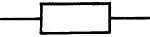
A resistor at constant temperature (ohmic conductor)

A Filament Lamp
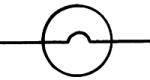
Here the graph curves because as the filament heats it’s resistance goes up (the resistance of the filament is changing). This is an ohimc conductor at a low voltage as that is where it follows Ohm's law.
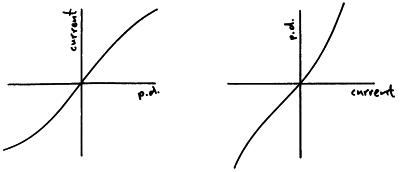
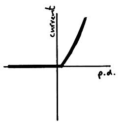
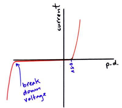
A diode
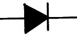
A diode only allows current to flow in one direction through it (forward biased), when the current tries to flow the other way (reverse biased) no current is allowed to flow through the diode. This is not an ohmic conductor as it does not follow Ohm's law.
When the diode is reversed biased if we keep increasing the potential difference the diode will eventually begin to conduct in the reverse direction, this is called the break down voltage.
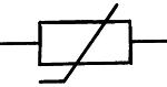
Thermistor
The resistance of a thermistor decreases as it’s temperature increases. Thermistors can be used as thermostats, the thermistor is used in circuits which monitor and control the temperature of rooms, freezers & fridges etc. This is not an ohmic conductor as it does not follow Ohm's law.

Thermistors can have a positive or a negative temperature coefficient. A negative temperature coefficient means that its resistance decreases with an increase in temperature, this is caused by the release of extra charge carriers in the thermistor.
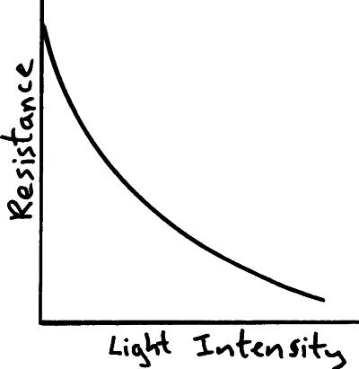
LDR – Light Dependant Resistor
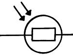
The resistance of an LDR decreases as the light intensity falling on it increases. LDR’s are used in circuits which automatically switch on lights when it gets dark, for example street lighting. This is not an ohmic conductor as it does not follow Ohm's law.
I found this video on YouTube and i thought it might help if you are still confused.
BY HARSHIL
Perhaps it would be worth noting that with the filament lamp the reason for the increase in resistance, and as such, change in the rate of V/I is due to the following:
ReplyDeleteHigher current creates higher temperature.
Higher temperature causes greater vibration of fixed ions in the metal.
This, in turn, increases the frequency of electron-ion collisions.
As a result a greater resistance is measured.